Trail Camera Security Box Size Chart: Which Box Fits Your Camera Model
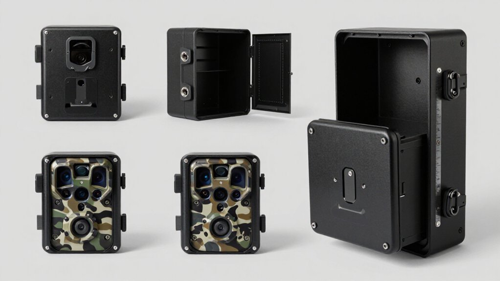
Match your camera’s exact SKU to Browning’s compatibility listing before choosing a security box. BTC-SB fits selected Command Ops HD, Recon Force, Spec Ops, and Patriot models; BTC-SB-SM fits compact Command Ops Pro, Strike Force, and Dark Ops units.
Pro Scout Cellular requires BTC-SB-PS, while BTC-SB-SM2 fits listed cellular series only. Confirm hole spacing, door closure, cable channels, and antenna/GPS cutouts before mounting. The fitment details below help you secure the camera without compromising operation.
BTC-SB Compatibility Index
Use Browning’s BTC-SB compatibility index to match the security box to your camera’s exact housing and mounting layout. The original BTC-SB secures Command Ops HD, Recon Force, Spec Ops, and Patriot units; verify the model label before ordering. For compact bodies, select the BTC-SB-SM only when your camera is a Command Ops Pro, Strike Force, or Dark Ops model. Don’t install it on Recon Force, Spec Ops, or Defender Wireless cameras; enclosure dimensions and attachment points won’t align correctly.
Pro Scout cellular cameras require the dedicated BTC-SB-PS. For any cellular Browning unit, confirm its exact SKU against the manufacturer’s current compatibility listing before deployment. This check prevents loose retention, blocked ports, misaligned cable routing, and weakened theft resistance during routine field checks after installation.
BTC-SB-SM2 Fitment Matrix
The BTC-SB-SM2 fits Browning cellular models that need unobstructed antenna and GPS signal paths, including BTC-PSM, BTC-PSMX, BTC-4G-V, BTC-VP, BTC-RLDCP, and BTC-DWPS series cameras. Verify your exact camera model before purchase; this box is engineered for cellular transmission and reception, with cut-outs that preserve built-in or external high-gain antenna and GPS paths.
| Model group | Listed fitment | Signal accommodation |
|---|---|---|
| BTC-PSM/BTC-PSMX | Compatible | Antenna/GPS cut-outs |
| BTC-4G-V/BTC-VP | Compatible | Antenna/GPS cut-outs |
| BTC-RLDCP/BTC-DWPS series | Compatible | Antenna/GPS cut-outs |
Its rugged camouflage exterior helps you conceal a purpose-built physical barrier in the field. At the listed $24.99 MSRP, you get model-specific protection instead of a generic enclosure. Confirm compatibility before deployment: an unsupported variant can misalign with the cut-outs, restricting antenna clearance, weakening reception, or reducing secure access to the camera housing.
Cable Lock Diameter Terms
Cable-lock diameter identifies the cable’s thickness, typically in inches or millimeters, and directly affects whether it will pass through a security box’s cable-lock channel. You should verify the channel’s internal dimensions before buying a cable lock. The cable must clear the channel without forcing, pinching, or preventing the lock mechanism from seating correctly.
At the same time, don’t select the smallest cable simply for easier routing; choose a diameter that provides appropriate cut resistance and durability for your deployment. Confirm those specifications with the manufacturer or measure the channel carefully. Record both the cable diameter and usable channel clearance, then leave modest tolerance.
Mounting-Hole Spacing Measurements
Measure mounting holes center to center to establish the box’s horizontal and vertical spacing. You should verify the manufacturer’s specifications and match them to your tree, post, or stand pattern before drilling. Leave sufficient installation clearance so fasteners and locks don’t obstruct secure access or camera operation.
Measuring Center-To-Center Spacing
Accurate center-to-center spacing guarantees the trail camera aligns with the security box’s mounting slots without forced fitment or weakened fastening. You locate each mounting hole’s midpoint, then measure directly between those two centers rather than between their outer edges. Use calipers for the reliable result, or use a ruler with graduations when calipers aren’t available.
Keep the tool straight and centered over each hole; angled placement creates error that can misalign the camera inside its enclosure. Record each applicable center-to-center measurement and compare it against the box’s slot or hole specifications before installation. Evaluate camera mounting holes independently: cable-lock channels and lag-screw provisions are separate security features, not spacing references. Confirm dimensions before drilling or tightening hardware, since improvised mounting can compromise tamper resistance.
Horizontal Hole Distance
Horizontal mounting-hole distance determines whether a security box aligns securely with the intended mounting surface. Before installation, verify the box’s horizontal hole spacing using the manufacturer’s product specifications or by measuring from the center of one mounting hole to the center of the other. Then match that measurement to the corresponding holes on your mounting surface.
This confirms alignment and helps prevent forced fitment, loose fastening, or weakened security. Don’t assume Browning BTC-SB, BTC-SB-SM, BTC-SB-SM2, and BTC-SB-PS boxes use identical horizontal spacing; each model requires verification. Also, don’t treat the listed 3/8-inch Browning measurement as mounting-hole distance. It identifies the padlock slot size, not the box’s mounting pattern. Record your confirmed measurement before drilling or selecting hardware for a secure installation on site.
Vertical Hole Distance
Vertical mounting-hole distance completes the fit check for a trail camera security box. Consult the specific box’s product page or manufacturer instructions for its hole-to-hole distance.
Measure from the center of the upper mounting hole straight down to the center of the lower mounting hole. Record the result accurately, using the same unit specified by the box documentation.
Before installation, confirm that this vertical spacing aligns with the available mounting points on your tree, post, or mounting bracket. Correct verification prevents forced fastener placement, unstable attachment, and security weaknesses that could compromise the protected camera. Don’t drill until you confirm the measured clearance.
Matching Box Mounting Patterns
Match the security box’s mounting-hole spacing to your camera’s mounting pattern before you buy or install it. Verify the manufacturer’s fit or compatibility listing for your exact model, because box dimensions and mounting patterns can vary. Don’t assume boxes from the same brand use identical hole locations; Browning, for example, makes separate boxes for Pro Scout and sub-micro series.
If possible, seat the camera in the box and align its mounting holes before installation. This confirms the enclosure matches the camera rather than merely resembling it externally. After you confirm alignment, inspect the box’s lag-screw points or cable-lock channels against your chosen surface and hardware. Use only mounting features that match the hardware’s placement and provide a secure attachment without forcing or modifying components.
Allowing Installation Clearance
Measure mounting-hole spacing from the center of each hole, then compare those dimensions with your camera’s mounting pattern before installation. Center-to-center measurements give you a consistent reference; edge-to-edge readings can vary with hole diameter and lead to misalignment. Verify that the enclosure holes align with your camera or mounting plate without forcing either component.
Leave enough clearance for screw heads, washers, and the mounting plate. These parts must not contact the box walls, pinch the camera, or prevent it from sitting squarely inside the enclosure. Confirm the camera’s mounting points remain aligned when you tighten hardware, since shifting can obstruct the lens, controls, or door. Before you buy, request hole-center dimensions from the manufacturer.
Reading Manufacturer Fitment Listings
Start with the camera’s exact model or series, then compare it to the security-box manufacturer’s compatibility list rather than relying on similar product names. Browning’s BTC-SB fits selected Command Ops HD, Recon Force, Spec Ops, and Patriot cameras. The BTC-SB-SM serves Command Ops Pro, Strike Force, and Dark Ops models; it does not fit Recon Force, Spec Ops, or Defender Wireless cameras. For cellular units, use BTC-SB-SM2 only with listed BTC-PSM/PSMX, BTC-4G-V, BTC-VP, BTC-RLDCP, and BTC-DWPS series.
BTC-SB-PS protects Pro Scout Cellular cameras only. When a listing directs you to verify fitment on the product page, confirm the full model designation before ordering. If you buy locally, place the camera in the box and check that it seats securely without shifting. A loose or mismatched box weakens tamper resistance and can prevent proper locking.
Do Not Block Antennas
For cellular trail cameras, use a security box that keeps antenna paths clear, since metal directly over or in front of an antenna can weaken cellular and GPS reception.
Choose a model-specific enclosure engineered to preserve signal transmission. Before installation, compare every antenna location with the box’s cut-outs and confirm they align without contact or partial coverage. A mismatched opening can reduce upload reliability and location performance.
The Browning BTC-SB-SM2 includes dedicated cellular and GPS cut-outs for compatible cameras, including units with built-in or external high-gain antennas. It fits specified BTC-PSM/PSMX, BTC-4G-V, BTC-VP, BTC-RLDCP, and BTC-DWPS series cameras. Verify your exact camera variant before mounting, because antenna placement can differ within a product line. Keep each opening unobstructed by the box and nearby metal.
Python Lock Field Setup
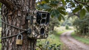
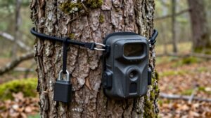
Once antenna cut-outs remain clear, secure the box with a Master Lock Python cable when the enclosure supports it; Browning doesn’t include the cable. Before deployment, inspect the security box for a dedicated cable-lock channel and confirm your Python cable passes through it without binding. Browning lists Python-cable compatibility for its Sub Micro Strike Force box; for every other model, verify compatibility before field setup.
Feed the cable through the locking channel, wrap it around a healthy, sturdy tree or a fixed steel post, and cinch it tightly to minimize slack. Position the camera at its intended angle before tightening. Verify the cable’s path cannot cross the lens, PIR sensors, or cellular and GPS antenna openings. Test installation by pulling firmly; reposition if it shifts.
Correcting Misaligned Door Latches
If the door latch won’t align, first confirm the trail camera sits fully and correctly in the security box and isn’t pressing against the door. Inspect the latch area before securing the unit; a poor closure reduces tamper resistance and weather protection.
- Open the door and verify the camera is seated squarely.
- Loosen mounting hardware slightly, then align the box body and door.
- Remove debris from the latch path and inspect the door edge for bends.
- Retighten hardware evenly and test latch engagement with the camera installed.
Check door movement after adjustment before tightening again. Don’t force latch or bend components to close it. Force can damage the catch or weaken security.
If alignment remains wrong, stop and contact manufacturer for model-specific repair guidance.
BTC-SB-PS Power Port Clearance
You must verify cable routing before deploying an external battery, solar panel, or other wired supply. An unsupported opening or cable route can weaken the enclosure and create a leverage point for tampering.
- Contact manufacturer and request confirmed port-side dimensions and cutout location.
- Measure camera plug, cable bend radius, and connector strain-relief depth.
- Confirm the door closes, locks, and doesn’t pinch the cable.
- Reject unverified installations; a forced cable path can compromise weather sealing and enclosure security.
Use only documented fitment data; otherwise, choose a box designed for your specific external-power configuration before field deployment for security and weather protection requirements.
Conclusion
Use the BTC-SB compatibility index and fitment matrices to match your camera’s body dimensions, door swing, antenna locations, and power-port position before you buy. You’ll improve theft resistance only when the box, cable lock, mounting pattern, and latch alignment work together. Verify lock diameter and hole spacing with measured values, not assumptions.
During installation, keep antennas and ports clear, correct latch misalignment, and test access. Your camera stays protected and functional in the field reliably.