Do Trail Camera Antenna Boosters Work? Real Signal Gains Explained
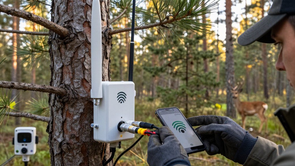
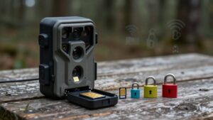
Trail camera antenna boosters work when you already have a weak, usable LTE carrier: an external antenna can improve received power and stabilize uploads, but it can’t create service in a dead zone.
Measure RSRP and SINR before and after installation; links near −113 dBm often remain unstable, while RSRP better than −100 dBm may see little change.
Match 50-ohm SMA connectors, LTE bands, antenna type, and coax length to preserve gain.
Setup details follow.
External Antennas Improve Weak LTE
External antennas can improve a trail camera’s LTE performance when the camera already detects a weak but usable carrier. They don’t generate cellular service; they capture existing RF energy more efficiently than the camera’s compact internal antenna. That distinction matters: if your site has no detectable carrier, an antenna cannot bridge a complete coverage gap.
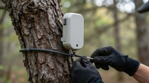
A remote-mount extended-range setup may provide 6 dBm or more of antenna gain before cable losses. Coaxial cable reduces that benefit: RG58 loses about 0.18 dB per foot, so 10.5 feet removes roughly 1.8 dB, leaving about 4.2 dB net.
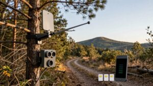
When you can identify and aim toward the nearest tower, a directional antenna often performs better. Improved line-of-sight and careful elevation can produce net gains near 8.3 dB overall.
RSRP, SINR, and Uploads
The measurable test of an antenna upgrade is whether it improves RSRP and SINR enough to stabilize uploads, not whether it adds another signal bar. RSRP measures received reference-signal power; SINR indicates how cleanly the camera separates that signal from interference and noise. You need both: decent bars can mask poor SINR, causing retries or failed image transfers.
If your camera already reads better than about −100 dBm RSRP, an upgrade may offer little benefit. Near −113 dBm, links often become unstable. A screw-on antenna may add roughly 1 to 3 dBm, while a properly placed remote directional antenna can deliver 5 to 8 dBm net. Those gains can reduce retransmissions and radio-on time, so your camera completes uploads more consistently and consumes less battery power per image.
SMA Mismatches at Remote Sites
At remote sites, a connector mismatch can erase an antenna upgrade’s expected gain before the camera sends its first image. Verify that your camera has a true SMA external port and that the antenna, cable, and adapter match its gender, polarity, and 50-ohm impedance. An SMA-to-N or reverse-polarity adapter stack adds insertion loss and contact points that can loosen or oxidize outdoors. Those losses can consume an expected 3 dBm improvement.
Poor matching raises VSWR, so passive boosters can’t deliver their advertised benefit; the receiver may see less usable signal instead of the expected 5 to 11 dBm net gain. Coax compounds the problem: 15 feet of RG58 costs about 2.7 dB at 0.18 dB per foot. Use a weatherproof matched cable or adapter, or performance may be worse than stock.
Omnidirectional vs. Yagi Antennas
You’ll get roughly 360° coverage from an omnidirectional antenna, but its typical 2 to 4 dBi gain suits sites where tower direction is uncertain or variable. A Yagi concentrates reception within a 30 to 120° beam and can deliver about 11 to 12 dBi improvement when you aim it precisely at the serving tower.
Choose a Yagi for a known tower and marginal signal, but expect limited results from either type near −113 dBm.
Coverage Pattern Differences
Although both types can improve a trail camera’s cellular link, they distribute gain very differently: an omnidirectional antenna sends and receives across 360° horizontally, typically at about 4–9 dBi, while a Yagi concentrates roughly 8–20+ dBi into a 30°–120° beam.
Your pattern determines where the link budget improves. An omni forms a doughnut-shaped horizontal field, whereas a Yagi’s main lobe directs reception toward the tower. At beam edges, Yagi response may fall 15–20 dB below peak; even small alignment errors thus reduce its advantage. Tests show roughly 11 dBi net directional improvement, compared with a practical omni benchmark near 4 dBi.
| Pattern | Horizontal coverage | Gain |
|---|---|---|
| Omni | 360° | 4–9 dBi |
| Yagi | 30°–120° | 8–20+ dBi |
That concentration increases range, but doesn’t help outside the aimed path.
When To Use Omnidirectional
Choose an omnidirectional antenna when you can’t confidently identify or aim toward the serving tower, or when the camera’s best signal path may change. An omni receives across roughly 360 degrees, so you don’t need a fixed bearing or repeated alignment after moving the camera. Typical models deliver 2 to 9 dBi, commonly 6 to 8 dBi; treat that as a modest link-budget improvement, not a cure for severe fringe coverage.
Measure RSRP at the camera before upgrading. If readings are better than about −100 dBm and uploads are stable, an omni is often sufficient. It can improve reception through better placement, a clearer mounting position, or added height, with about 0.5 to 1 bar improvement plausible. Verify performance using RSRP, upload success rate, and reconnect frequency over several days.
When Yagi Antennas Excel
A Yagi antenna excels when you can identify a serving tower and need more gain than an omnidirectional model can provide. Unlike an omni’s roughly 360-degree coverage, a Yagi concentrates transmit and receive energy within about 30 to 120 degrees. In favorable cellular bands, it can deliver about 11 dBi versus an omni’s approximate 4 dBi, raising RSRP in the aimed direction.
You’ll need precise alignment: sweep the full horizon in 10-degree increments, then peak the reading at the camera. Install it high enough, often near 15 feet, to clear local obstructions and preserve a reasonably line-of-sight path; terrain still limits performance. Validate results with RSRP, not bars. A useful outcome is RSRP better than −100 dBm or an improvement exceeding 1 to 3 dBm under real field conditions.
Carrier Band and Tower Load
You must match your antenna to the LTE bands your carrier and nearby tower support; gain won’t help if the camera can’t lock onto that frequency. Even with unchanged RSRP or signal bars, tower congestion can reduce SINR and throughput, causing failed or slow uploads.
Check your camera’s supported LTE bands, then use a matched directional antenna, often about 11 dBi minus 2.7 dB cable loss, to improve link stability under load.
Matching Antenna To Carrier Bands
Why does one antenna improve a trail camera’s connection while another with a higher advertised dBi rating does nothing? Because gain only matters on frequencies your camera and serving tower actually use. Check the carrier’s LTE or 5G bands at the camera location, then choose an antenna rated across those bands; broad LTE coverage is usually safer than a narrow design.
An out-of-band antenna can’t convert its published dBi into usable receive sensitivity, so dBm may barely move after installation. Mount and aim a directional model toward the dominant signal path; correct placement can produce roughly 8.3 dB net gain. Measure RSRP at the camera, not your truck, and look for improvement toward better than about −100 dBm. Signal bars can mislead when SINR changes.
Tower Congestion Limits Performance
Even with an ideally matched antenna, tower congestion can cap a trail camera’s upload speed because every device on that carrier and sector competes for finite radio scheduling and backhaul capacity.
You may see strong RSRP yet slow uploads when peak demand lowers SINR; bars don’t measure scheduler availability. A booster can improve link margin, not carrier scheduling, backhaul, or throttling. A 1–3 dB gain (roughly 0.5–1 bar) often won’t offset congestion.
Compare results across times: similar dBm can produce different throughput by carrier and frequency range.
| Observation | What it indicates |
|---|---|
| Strong RSRP, low SINR | Loaded radio sector |
| Fast overnight uploads | Lower tower demand |
| Slow uploads at peak | Scheduling/backhaul limit |
| Small dB gain, no speed gain | Congestion dominates |
Test repeatedly before judging antenna value.
Checking Supported LTE Bands
Before evaluating a trail camera antenna booster, confirm the camera’s supported LTE bands and the band it actually uses at the site. Check band numbers and frequencies, including 700, 850, 1700, 1900, and 2600 MHz. A booster improves only frequencies within its rated coverage. Use the camera’s network screen to record its active LTE band, RSRP, and SINR, then match that band to your carrier’s local tower allocation. If the camera connects on an unsupported band, advertised gain is irrelevant. Also account for tower load: congestion can lower SINR, throughput, and displayed bars even when band matching is correct. Because carriers can shift allocations or serve multiple bands, choose an antenna with broad LTE bandwidth rather than a narrowband model. Retest at different times.
Monitoring a Backcountry Food Plot
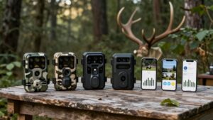
Monitoring a backcountry food plot with a cellular trail camera starts with verifying that the site has a usable LTE path, not simply adding an antenna booster. Measure RSRP before upgrades: target better than −100 dBm, or a steady three bars, to limit retries and missed uploads.
| Check | Field target |
|---|---|
| Baseline | >−100 dBm |
| Screw-on | 1 to 3 dBm |
| Directional net | 8.3 dBm |
| RG58, 15 ft | −2.7 dBm |
At wooded plots, mount a directional antenna higher, then aim it toward the tower. This placement can outperform a screw-on unit because clearance improves the path. Keep cable runs short: RG58 loses 0.18 dB per foot, so 15 feet costs roughly 2.7 dB. Record RSRP and upload reliability after adjustment, and retain the position that reduces retries most consistently.
Antennas Cannot Create Signal
A trail-camera antenna can’t create cellular signal; it can only capture the tower signal already present more efficiently. Your camera’s antenna is a passive receiver, not an amplifier that adds power to the carrier’s transmission. Its gain describes how it concentrates received radio-frequency energy in a useful direction or improves effective sensitivity.
That efficiency can matter. If your existing setup reads a weak RSRP and a replacement improves reception by 1 to 3 dB, you may gain roughly 0.5 to 1 bar and move closer to a workable −100 dBm RSRP target. Larger directional antennas can deliver higher gains when aimed correctly. But an antenna can’t turn near-zero coverage into service. Around the practical lower edge of usability, approximately −113 dBm RSRP, there’s too little recoverable signal. It captures energy; it doesn’t manufacture it.
Mounting Antennas Behind Metal
Behind metal, a cellular antenna can lose much or all of its usable signal path. Metal blocks or sharply attenuates RF; your antenna can’t create signal that never reaches it. A correctly connected antenna may consequently produce lower camera readings, often a several-dB RSRP decline and an apparent one to two bar loss.
- A license-plate bracket can shadow the antenna.
- Foil-backed tape can interrupt the incoming RF path.
- A metal camera housing can screen the antenna.
- A directional antenna loses focused-lobe benefit when metal blocks its tower-facing side.
Even small metal pieces can cause this effect because their placement alters the antenna’s line of sight and field pattern. Reposition it outside, clear of metal, then compare camera readings. Better than roughly −100 dBm RSRP indicates usable link.
Measure Coax Run Before Ordering
Before ordering a booster or remote antenna, measure the exact coax route and record the camera’s current RSRP/RSSI at that location. Confirm the run, rather than a weak coverage area, limits performance. Mark every bend, slack loop, and strain-relief section. RG58 loses about 0.18 dB per foot, so cable can erase antenna gain.
| Run | Estimated RG58 loss |
|---|---|
| 10.5 ft | 1.8 dB |
| 15 ft | 2.7 dB |
| Extra foot | 0.18 dB |
| Target RSRP | Better than -100 dBm |
Test the planned antenna position with a shorter run. If RSRP improves by the expected cable-loss difference, placement and coax are the problem. If readings remain near -113 dBm, you have no reliable connection; a booster won’t materially help. Choose a verified shorter route before you buy equipment instead.
Conclusion
Trail camera antenna boosters work only when you improve the radio path, not when you expect them to create service. You’ll gain the most by measuring RSRP and SINR, matching SMA connectors, selecting an omni or Yagi for your terrain and carrier band, and minimizing coax loss. Don’t mount antennas behind metal or ignore tower congestion. Before you order, measure the cable run and test uploads at the food plot. Data, not marketing, determines results.